Created by - Anil Chauhan
Introduction to Autodesk Maya
Introduction to Autodesk MayaAutodesk Maya is a powerful 3D computer graphics software used for creating interactive 3D applications, including video games, animated films, TV series, and visual effects. It is widely recognized as one of the industry-standard software for 3D modeling, animation, simulation, and rendering. Maya is known for its comprehensive set of tools, versatility, and high-quality output, making it essential for professionals in the fields of animation, VFX, game development, and 3D visualization.Here is a breakdown of the core features and concepts in Autodesk Maya:1. 3D ModelingMaya allows users to create 3D models of characters, environments, and objects using various tools: Polygonal Modeling: The creation of 3D objects using polygons, such as squares, triangles, and other shapes. This is the most commonly used method for hard surface modeling. NURBS (Non-Uniform Rational B-Splines): A mathematical method for creating smooth curves and surfaces, often used in industrial design and automotive modeling. Subdivision Surfaces: This technique allows for smoother surfaces when subdivided, giving more control over organic shapes, often used in character modeling. 2. AnimationMaya is particularly renowned for its animation tools, which allow users to bring 3D models to life: Keyframing: Setting specific points of motion for objects in a timeline. Maya interpolates the motion between keyframes to create smooth animations. Rigging: Creating a skeletal structure for a 3D model (such as a character), which allows for easier manipulation of the model for animation. Character Animation: With Maya, animators can control characters through inverse kinematics (IK), forward kinematics (FK), facial rigging, and motion capture integration. Blend Shapes: Used to animate facial expressions and other deformations by blending different shapes of the same model. 3. Texturing and ShadingTexturing refers to adding details like color, texture, and surface properties to a 3D model. Maya supports: UV Mapping: Unwrapping a 3D model’s surface to apply textures. Shading: Using shaders to define how a surface interacts with light, including effects like reflections, transparency, and glossiness. Substance Integration: Maya integrates with Substance Painter, allowing users to texture 3D models with high-quality materials and advanced texture painting techniques. 4. Lighting and RenderingMaya provides powerful rendering features, making it suitable for both high-quality and real-time rendering: Lighting: Adding light sources to a scene, including point lights, spotlights, directional lights, and area lights. The choice of light affects the look and feel of the scene. Rendering Engines: Maya supports different rendering engines like Arnold (integrated with Maya), mental ray, and others. Arnold, in particular, is used for creating photorealistic images and animations. Global Illumination: Simulating how light interacts with surfaces, resulting in more realistic lighting and shading effects. Render Layers and Passes: Organizing different elements (such as shadows, reflections, and diffuse colors) into separate layers for greater control during post-production. 5. Dynamics and SimulationMaya includes tools for simulating real-world physics: Particle Systems: Simulating smoke, fire, explosions, and other effects that involve numerous particles. Cloth Simulation: Using the nCloth system to simulate realistic fabric behavior. Hair and Fur: Maya's XGen allows artists to create realistic hair and fur for characters or environments. Fluid and Rigid Body Dynamics: For simulating liquid, gas, and solid objects interacting with each other in realistic ways. 6. MEL and Python ScriptingMaya supports scripting languages like MEL (Maya Embedded Language) and Python to automate tasks and extend its functionality. Users can write scripts to control the software, create custom tools, and improve their workflow.7. Plugins and ExtensionsMaya is highly extensible, offering a range of third-party plugins to enhance its functionality. Popular plugins include those for creating advanced simulations, rendering, and character animation tools.8. InteroperabilityMaya supports file exchange with other software such as: Autodesk 3ds Max for cross-platform workflows. ZBrush for high-resolution sculpting. Unity and Unreal Engine for game development integration. Industries and Applications Animation: Maya is used to create animated characters, environments, and visual effects for films and television series. Video Games: It is heavily used for modeling, rigging, and animating characters, environments, and props for video games. VFX: Maya plays a critical role in creating visual effects for blockbuster movies, including simulations like smoke, fire, explosions, and realistic lighting. Architecture and Product Design: In industries like architecture and industrial design, Maya is used for visualization, prototyping, and rendering. Conclusion Autodesk Maya is a comprehensive and versatile software package, offering everything from basic 3D modeling to advanced character animation, VFX, and rendering tools. Its robust feature set and industry-standard status make it an essential tool for 3D artists, animators, and visual effects professionals around the world.
More detailsPublished - Mon, 06 Jan 2025
Created by - Anil Chauhan
Main Menu Bar
The user interface (UI) of Autodesk Maya is designed to provide an efficient and customizable workspace for 3D modeling, animation, and visual effects creation. The interface is divided into various panels and elements, allowing users to access a wide range of tools and features. Here's a breakdown of the key components of Maya's user interface:1. Main Menu Bar Located at the top of the interface, the Main Menu Bar includes menus such as File, Edit, Create, Modify, and Windows. These menus provide access to fundamental functions like opening and saving files, creating objects, and modifying scenes. 2. Shelf The Shelf is a toolbar just below the menu bar, containing customizable icons and shortcuts for commonly used tools. Users can add and organize icons for quick access to functions like rendering, modeling, animation, and simulation. You can create custom shelves to streamline your workflow. 3. Viewport The Viewport is the main display area where users interact with their 3D scene. You can view and manipulate objects in the scene using various camera views (perspective, top, front, side, etc.). It supports multiple views and display modes (wireframe, shaded, textured) to help visualize different stages of the modeling or animation process. 4. Channel Box / Layer Editor The Channel Box displays and allows users to modify the attributes of selected objects, such as position, rotation, scale, and material properties. It's a convenient panel for making quick adjustments. The Layer Editor allows users to manage and organize different scene elements into layers, enabling the toggling of visibility, selection, and editing for various elements within the scene. 5. Attribute Editor The Attribute Editor provides detailed control over the properties of selected objects, materials, lights, cameras, and other scene components. It displays all available attributes for the object, enabling precise adjustments. 6. Outliner The Outliner is a hierarchical view of all the objects in your scene. It allows users to organize and manage objects, lights, cameras, and more. It’s especially useful for large scenes with many elements, making it easy to select, rename, or group objects. 7. Toolbox The Toolbox (usually on the left side) contains essential tools for 3D manipulation, such as the select tool, move tool, rotate tool, scale tool, and paint tools. It also includes more specialized tools for sculpting, drawing curves, and more. 8. Time Slider The Time Slider at the bottom of the screen is used for animation. It displays the timeline of keyframes and allows users to scrub through the animation, play, pause, or set keyframes at specific points. 9. Status Line The Status Line at the top provides quick access to key functions such as saving, undoing, and redoing actions. It also displays important status information, like the current scene’s frame rate and status of the rendering process. 10. Perspective / Camera Views Maya's default view is the Perspective View, which allows users to navigate a 3D scene interactively. You can switch to Orthographic Views (front, side, top) for precise modeling. Multiple viewports can be opened to show different perspectives simultaneously. 11. Rendering and Display Panels The Rendering Panels are found in the main menu bar, allowing users to access rendering options such as Arnold, Render View, and Render Settings. These settings enable users to set up and preview rendered images or animations. 12. Viewport Controls Users can customize the appearance of the Viewport by adjusting lighting, shading, and display modes. The Viewport can show models in wireframe, shaded, textured, or rendered mode, giving users flexibility to work with different visual representations of their scene. 13. Script Editor The Script Editor is located at the bottom of the interface and provides a place to write, execute, and debug MEL (Maya Embedded Language) or Python scripts. It displays output messages and errors, enabling automation and customization of tasks. 14. Help and Documentation The Help Menu provides access to Maya's documentation, tutorials, and community resources, which are useful for learning and troubleshooting. 15. Status and Notifications In the lower-right corner, the status bar and notifications display important information about the scene, such as whether a rendering is in progress, or when a task has been completed. 16. Viewport Menu Users can right-click in the viewport to access additional options, including visibility controls, render settings, and more. Customization and Layouts:Maya's interface is highly customizable, allowing users to arrange and resize panels, and even create multiple workspace layouts for different tasks. Whether you're working on modeling, animation, or simulation, you can adjust the UI to suit your specific workflow.Conclusion: Maya’s user interface is designed for efficiency and flexibility. Its modular approach allows for a tailored workflow suited to individual preferences, whether you are a beginner or a professional. Through its panels, tools, and customizable layout, Maya provides artists with the necessary functionality to work with complex 3D projects.
More detailsPublished - Mon, 06 Jan 2025
Created by - Anil Chauhan
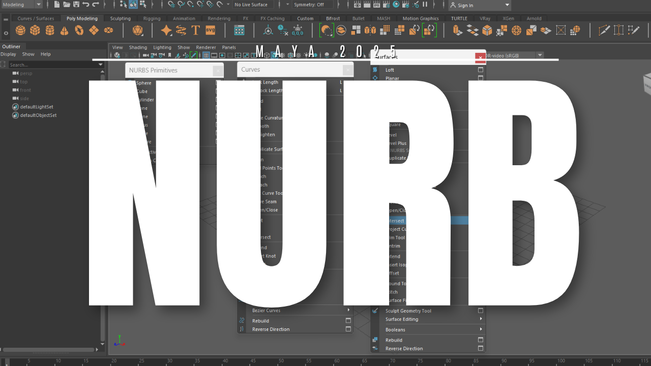
NURBS
NURBSNURBS (Non-Uniform Rational B-Splines) are mathematical representations used extensively in computer graphics, computer-aided design (CAD), and computer-aided manufacturing (CAM). They offer a powerful and flexible way to model curves and surfaces, providing high precision and smoothness.Key Concepts of NURBS1. NURBS Curves A NURBS curve is defined by: Control Points: These determine the shape of the curve. The curve does not necessarily pass through all control points but is influenced by them. Degree (Order): The degree of the polynomial basis functions used to define the curve. Common degrees are linear (1), quadratic (2), and cubic (3). Knots: A sequence of parameter values that determine how the basis functions blend. The sequence can be uniform or non-uniform. Weights: These allow for greater flexibility, enabling the representation of conic sections (e.g., circles, ellipses). Formula for a NURBS Curve: C(u)=∑i=0nNi,p(u)wiPi∑i=0nNi,p(u)wiC(u) = \frac{\sum_{i=0}^{n} N_{i,p}(u) w_i P_i}{\sum_{i=0}^{n} N_{i,p}(u) w_i} Where: C(u)C(u): The curve point at parameter uu Ni,p(u)N_{i,p}(u): The ii-th B-spline basis function of degree pp wiw_i: The weight of the ii-th control point PiP_i: The ii-th control point 2. NURBS Surfaces A NURBS surface extends the concept of NURBS curves to two parameters, uu and vv. Defined by: A grid of control points. Degree in the uu- and vv-directions. Knot vectors for each direction. Weights for each control point. Formula for a NURBS Surface: S(u,v)=∑i=0n∑j=0mNi,p(u)Mj,q(v)wi,jPi,j∑i=0n∑j=0mNi,p(u)Mj,q(v)wi,jS(u, v) = \frac{\sum_{i=0}^{n} \sum_{j=0}^{m} N_{i,p}(u) M_{j,q}(v) w_{i,j} P_{i,j}}{\sum_{i=0}^{n} \sum_{j=0}^{m} N_{i,p}(u) M_{j,q}(v) w_{i,j}} Where: S(u,v)S(u, v): Surface point at parameters uu and vv Ni,p(u)N_{i,p}(u), Mj,q(v)M_{j,q}(v): Basis functions in uu and vv directions wi,jw_{i,j}: Weight of control point Pi,jP_{i,j} Advantages of NURBS Flexibility: Can represent a wide range of shapes, from simple lines to complex freeform surfaces. Precision: Supports exact representations of standard geometric entities (e.g., circles, ellipses, parabolas). Smoothness: Provides smooth and continuous surfaces, ideal for CAD and 3D modeling. Compactness: Efficiently represents complex models with fewer data points compared to alternatives like meshes. Applications Automotive and Aerospace Design: Designing smooth and aerodynamic surfaces. Animation and 3D Modeling: Creating realistic characters and objects. Architectural Design: Modeling intricate curves and surfaces. Medical Imaging: Representing anatomical shapes. NURBS primitivesNURBS primitives are basic shapes or components that can be defined using NURBS representations. These primitives are the building blocks for more complex models and surfaces in applications like CAD, 3D modeling, and animation. The main components of NURBS primitives are:1. Control Points (Vertices) Definition: Points in 2D or 3D space that define the shape of the NURBS curve or surface. Role: The curve or surface is influenced by these points but does not necessarily pass through them. Moving a control point alters the overall shape. Grid Layout: For surfaces, control points are arranged in a grid, creating a control net. 2. Knot Vector Definition: A sequence of parameter values that define how control points influence the curve or surface. Types: Uniform Knot Vector: Knots are evenly spaced. Simplifies the blending functions but limits flexibility. Non-Uniform Knot Vector: Knots are not evenly spaced, providing more control over the curve or surface. Clamped Knot Vector: Ensures that the curve or surface starts and ends at the first and last control points. Purpose: Determines how basis functions blend. Affects the smoothness and continuity of the curve or surface. 3. Weights Definition: Scalar values associated with each control point. Role: Adjust the influence of a control point on the curve or surface. Higher weights pull the curve or surface closer to the corresponding control point. Enable the representation of conic sections like circles, ellipses, and parabolas. 4. Basis Functions Definition: Mathematical functions (B-splines) that define how control points influence the curve or surface. Characteristics: Controlled by the degree of the NURBS (e.g., linear, quadratic, cubic). Basis functions ensure local control, meaning changes to a control point affect only a portion of the curve or surface. 5. Degree Definition: The degree of the polynomial basis functions. Common Degrees: Linear (11): Straight-line segments. Quadratic (22): Parabolic segments. Cubic (33): Smooth curves widely used in design. Role: Higher degrees result in smoother and more flexible curves or surfaces. 6. Parameter Domain Definition: The range of parameter values (uu for curves; u,vu, v for surfaces) over which the curve or surface is evaluated. Role: Used for evaluating points on the curve or surface. NURBS Primitive Examples NURBS Curves: Open Curve: Does not form a loop. Closed Curve: Forms a loop but is not necessarily continuous. Periodic Curve: A closed curve with continuous derivatives. NURBS Surfaces: Plane: Flat, rectangular surface. Cylinder: Surface generated by sweeping a circle along a straight line. Sphere: Surface defined by rotating a circular arc. Would you like further details on any of these components or examples of how they work in practice?
More detailsPublished - Wed, 22 Jan 2025
Created by - Anil Chauhan
NURBS Curves,Components &,Surfaces
Maya's NURBS (Non-Uniform Rational B-Splines) system is a powerful way to create smooth and mathematically precise 3D surfaces. It is widely used in industrial design, animation, and visual effects.1. NURBS CurvesNURBS curves are the foundation of NURBS modeling in Maya. They are used to create and edit surfaces.Types of NURBS Curves in Maya: CV Curve Tool – Draws a curve by placing control vertices (CVs). EP Curve Tool – Creates curves based on edit points (EPs), which define the shape. Bezier Curve Tool – Uses Bezier handles to control the curve shape. Editing Curves Control Vertices (CVs) – Points that control the curve’s shape. Edit Points (EPs) – Points on the curve that define its structure. Curve Degree – Determines smoothness (Degree 1 = straight lines, Degree 3 = smooth curves). Rebuild Curve – Reconstructs curves for better uniformity. 2. NURBS ComponentsNURBS surfaces in Maya are made up of several key components: Control Vertices (CVs): Define the shape of the surface. Isoparms: Visual lines running along the U and V directions of a surface. Hulls: Groups of CVs that help in adjusting the surface as a whole. Surface Normals: Indicate the surface’s direction (useful for shading/rendering). 3. NURBS SurfacesNURBS surfaces are created using various techniques:Surface Creation Methods Loft: Creates a surface between two or more curves. Revolve: Spins a profile curve around an axis to create a surface (e.g., a vase). Extrude: Extends a curve along a path. Planar: Fills a closed curve with a flat surface. Birail: Uses two rail curves and a profile curve to create a surface. Editing NURBS Surfaces Trim Tool: Cuts out sections of a NURBS surface. Attach/Detach Surfaces: Combines or splits NURBS surfaces. Rebuild Surface: Adjusts the resolution and smoothness of a surface. Convert NURBS to Polygons: Useful for game engines and further detailing. When to Use NURBS✅ Ideal for smooth, organic shapes (cars, aircraft, bottles). ✅ Used in high-end modeling workflows for animation & product design. ✅ Provides precise control over curvature and topology.???? Not great for detailed sculpting or hard surface modeling (polygons are preferred). ???? More complex to UV map compared to polygons. Would you like help with a specific NURBS modeling task in Maya? ????
More detailsPublished - 7 Days Ago
Created by - Anil Chauhan
Introduction to Poly Tools and Prop Modeling in Maya
In Autodesk Maya, a polygon is a type of 3D geometry made up of vertices, edges, and faces. Polygons are widely used in modeling because they are efficient, flexible, and work well with real-time rendering engines.Basic Components of Polygons Vertices – Points in 3D space that define the shape of a polygon. Edges – Lines connecting two vertices. Faces – The flat surfaces enclosed by edges, usually forming triangles or quads. Normals – Directions that define how light interacts with the surface. Creating Polygon ObjectsIn Maya, you can create polygonal objects using: Create → Polygon Primitives (Cube, Sphere, Cylinder, etc.) Mesh Tools (Extrude, Bevel, Bridge, etc.) Boolean Operations (Union, Difference, Intersection) Polygon Editing Extrude – Extends a face or edge to create more geometry. Bevel – Softens sharp edges by adding extra edges. Merge – Joins vertices or edges together. Delete Edge/Vertex – Removes unwanted components. Insert Edge Loop – Adds more detail to the mesh. Polygon Display & Optimization Normals – Control the shading of surfaces. Wireframe Mode (4 Key) – Shows only edges and vertices. Smooth Shading (5 Key) – Displays shaded surfaces. Smooth Mesh Preview (3 Key) – Shows a high-poly preview. Cleanup Tool – Helps detect and fix geometry issues. Introduction to Poly Tools and Prop Modeling in MayaPoly Tools in Autodesk Maya are essential for creating 3D models using polygonal geometry. When modeling props, such as furniture, weapons, or environment assets, poly tools allow for efficient and detailed designs.1. Understanding Polygon ModelingPolygon modeling in Maya is based on creating and manipulating vertices, edges, and faces to shape 3D objects.Basic Polygon Primitives for Prop Modeling:Maya provides primitive shapes as a starting point: Cube – Useful for furniture, buildings, and mechanical objects. Sphere – Great for round objects like balls, fruits, or globes. Cylinder – Used for pipes, barrels, or columns. Plane – Commonly used for walls, floors, or cloth-like objects. 2. Essential Poly Tools for Prop ModelingA. Creation & Editing Tools Extrude (Ctrl + E) – Extends faces or edges to create additional geometry (e.g., legs of a chair). Bevel (Ctrl + B) – Softens sharp edges by adding edge loops (useful for realistic props). Insert Edge Loop (Shift + Right-Click → Insert Edge Loop Tool) – Adds more topology for better control. Multi-Cut Tool (Shift + Right-Click → Multi-Cut Tool) – Custom edge cuts for precise modeling. B. Mesh Optimization & Cleanup Merge (Edit Mesh → Merge) – Joins vertices or edges to remove gaps. Delete Edge/Vertex (Ctrl + Delete) – Removes unnecessary geometry. Smooth (Mesh → Smooth) – Adds subdivisions for a higher-poly look. Normals (Mesh Display → Reverse Normals) – Fixes shading issues. 3. Prop Modeling WorkflowStep 1: Block Out the Shape Start with basic primitives (cube, cylinder, etc.). Use Move (W), Rotate (E), and Scale (R) to position elements. Step 2: Add Details Use Extrude, Bevel, and Edge Loops to refine the shape. Adjust vertices and edges for accuracy. Step 3: Optimize the Mesh Remove unnecessary faces and edges. Check the topology (keep quads where possible). Step 4: UV Unwrapping (Preparation for Texturing) Use Automatic, Planar, or UV Editor to unwrap the model for texturing. Step 5: Apply Materials & Textures Assign shaders like Lambert, Blinn, or AI Standard Surface for realism. Use Hypershade to connect textures. 4. Best Practices for Prop Modeling✔ Keep Topology Clean – Use quads instead of triangles when possible. ✔ Use Edge Loops Wisely – Helps in deformation and subdivision. ✔ Reference Real-World Objects – Increases realism and accuracy. ✔ Optimize for Game or Film – Consider poly count and performance. Would you like a hands-on tutorial for a specific prop? ????
More detailsPublished - 2 Days Ago
Search
Popular categories
Adobe After Effects 2025
28Unreal Engine
14zbrush
10Maya Animation
8zbrush tutorial jewelry
7Maya 2025
5Latest blogs

Advanced Editing Techniques
53 Minutes Ago
Introduction to Level Design Through Blocking in Unreal Engine
1 Day Ago
Nuke, animating parameters
1 Day Ago
Write a public review